Getting authentic Atari joysticks working via a USB port.
Adapter has been tested on the following systems:
- Linux Mint 19
- MiSTer (Terasic DE10-Nano)
Parts:
- Pro Micro ATmega32U4 5V 16MHz - eBay.com $3.70
- 2 x DB9 RS232 Male Serial Connectors - eBay.com $2.80
- Enclosure (85mm x 50mm x 21mm) - eBay.com $1.00
- Micro USB Cable - eBay.com $1.50
Here are the pictures showing individual components, the prototype, as well as the finished adapter.
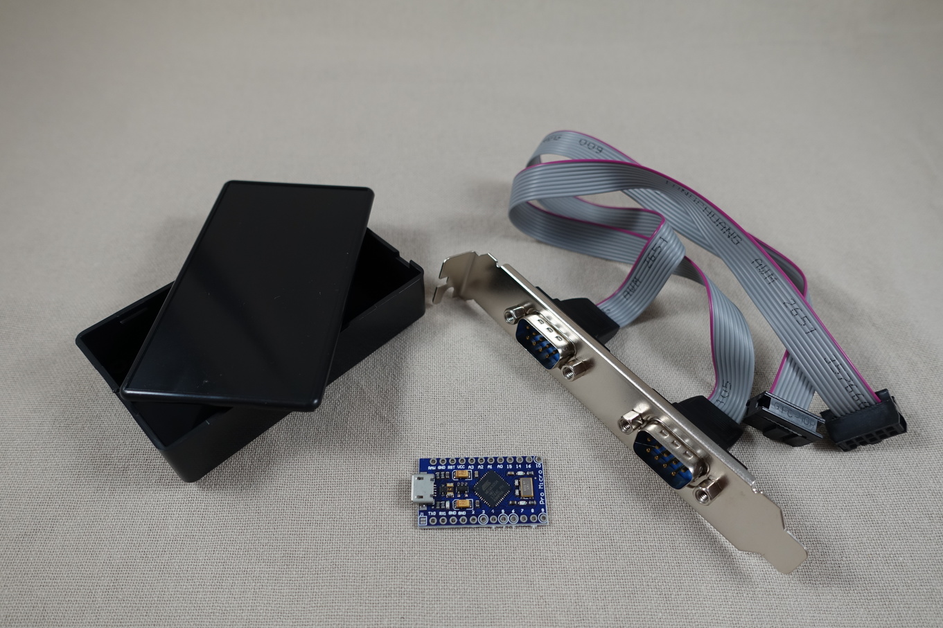
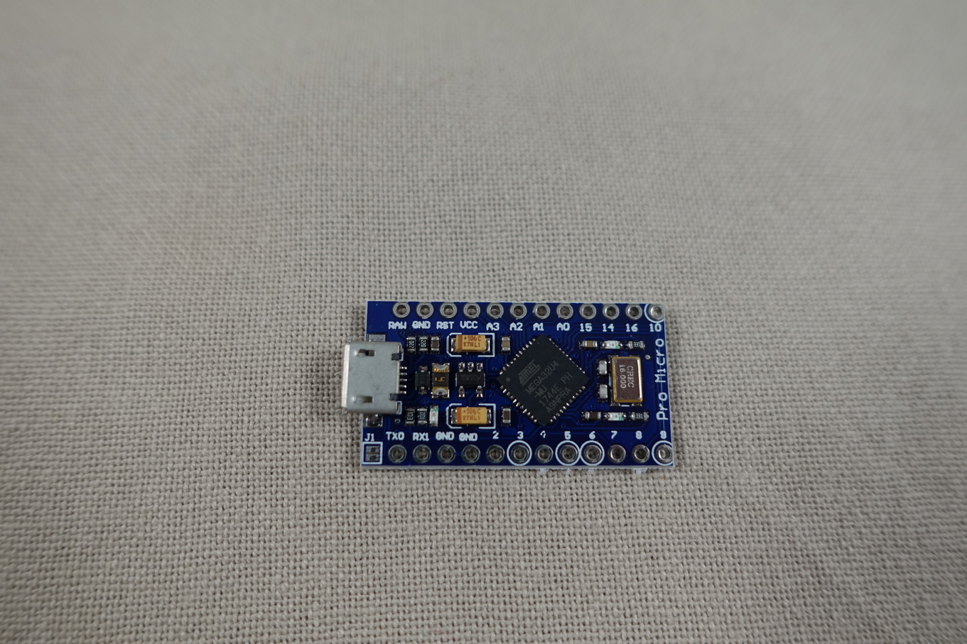
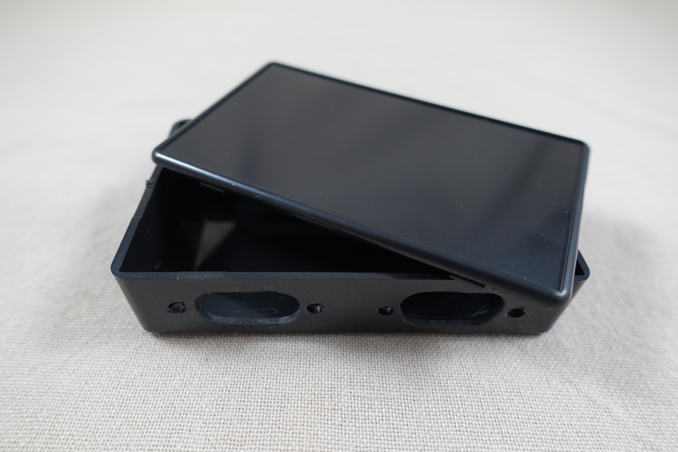
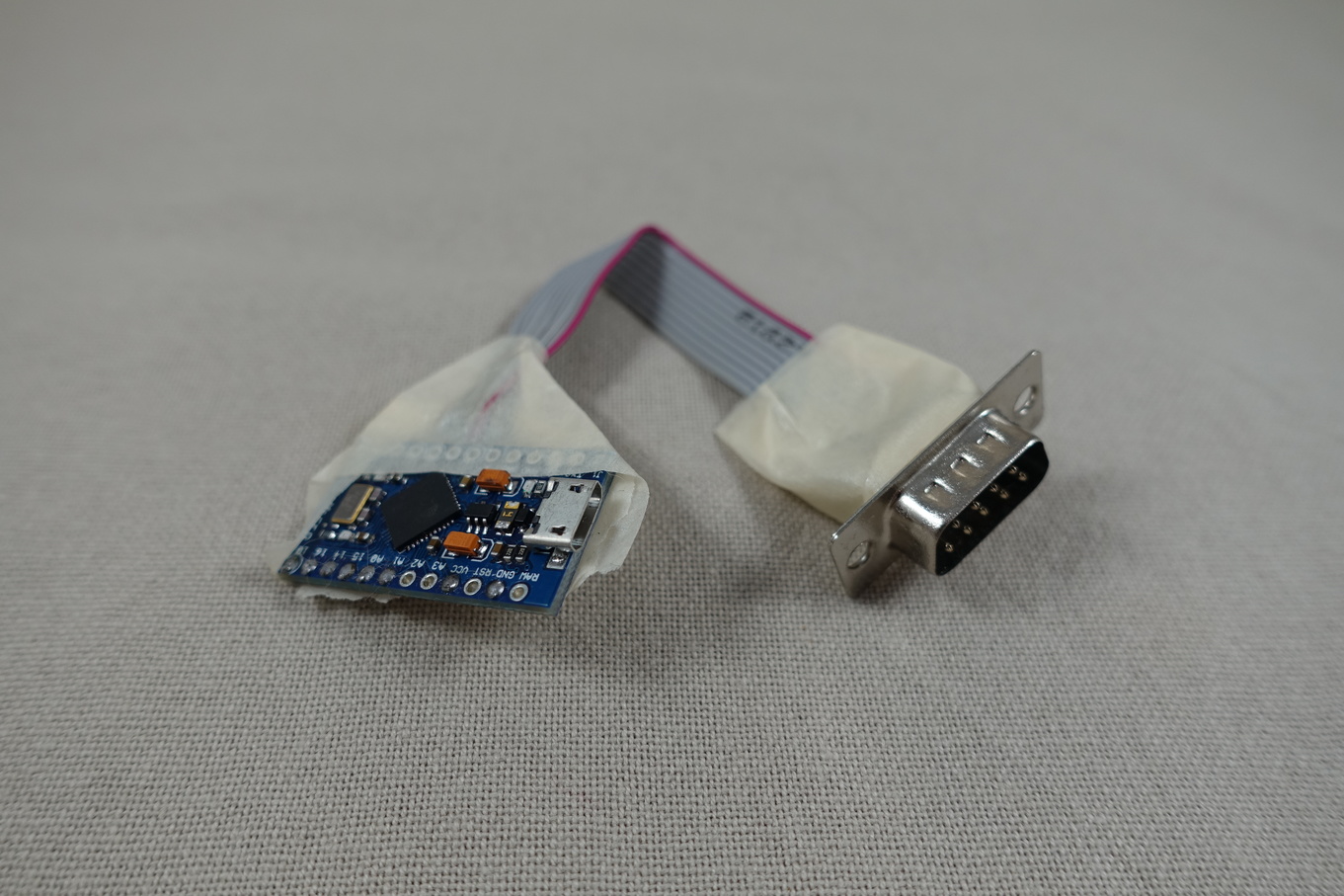
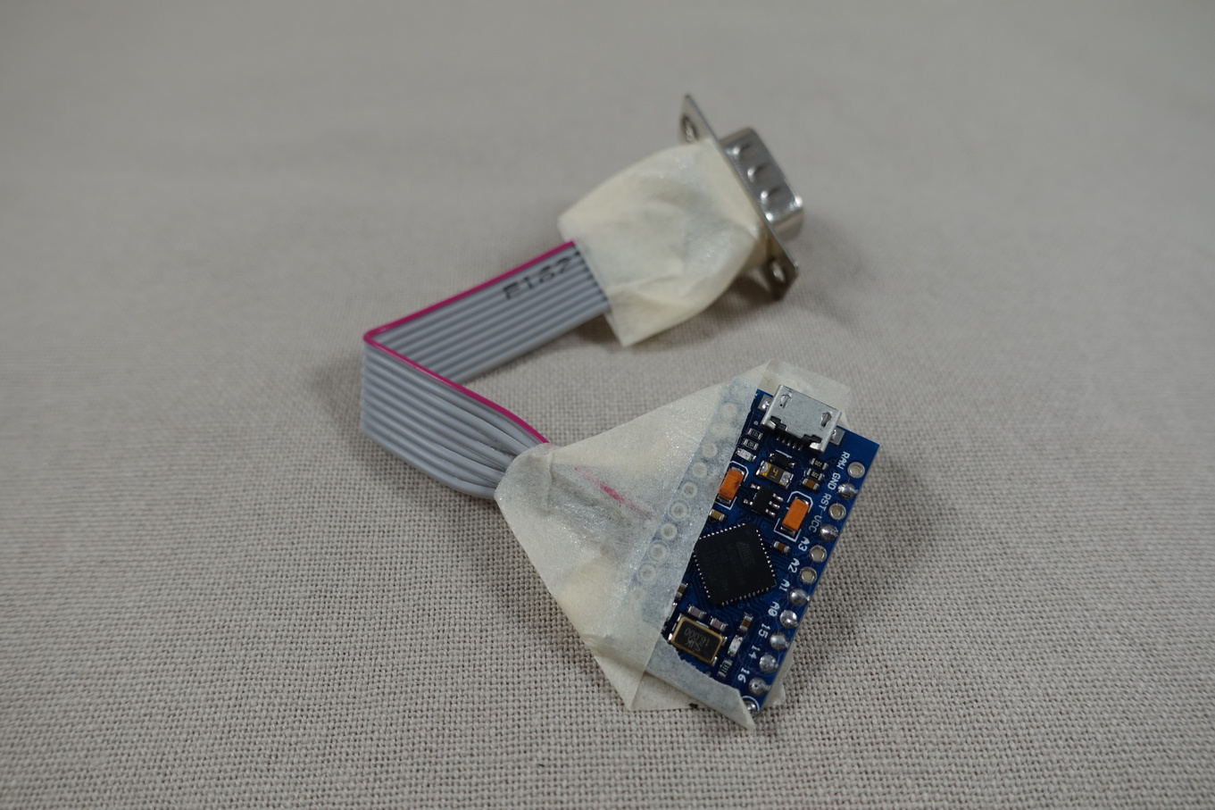
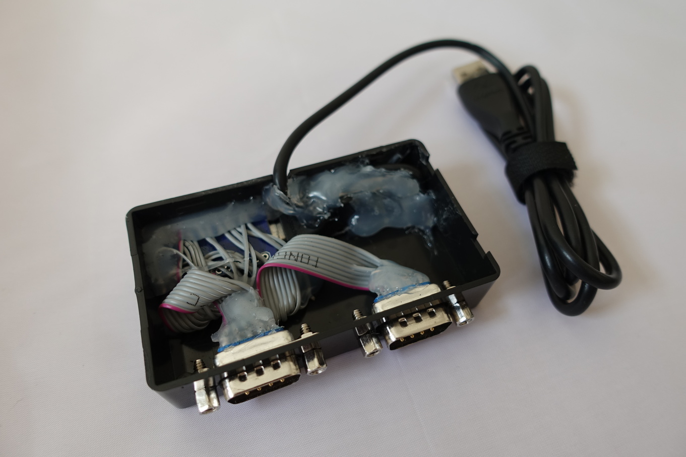
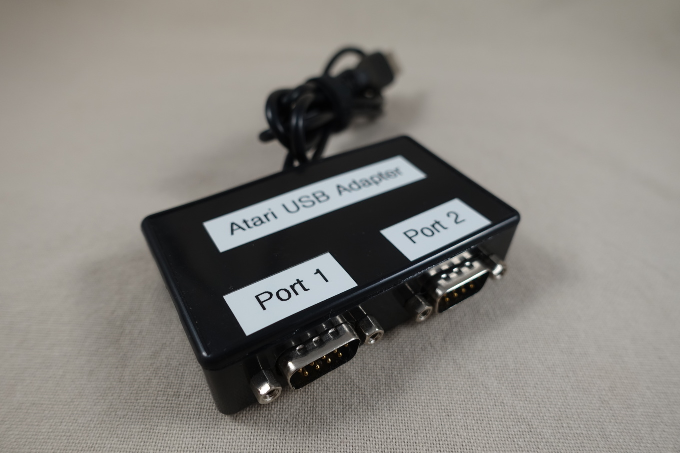
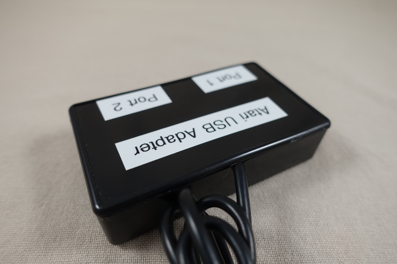
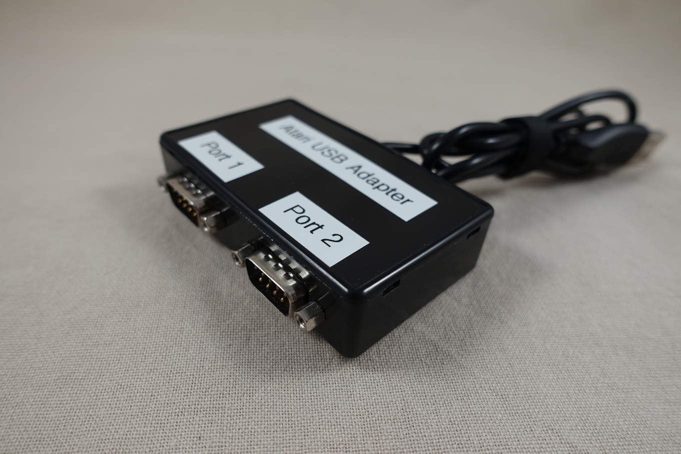
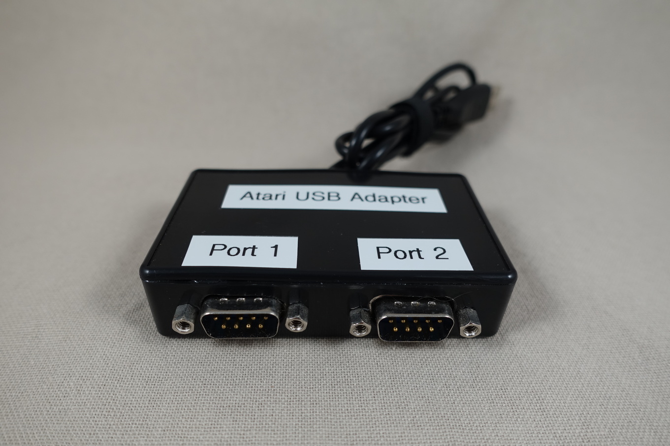
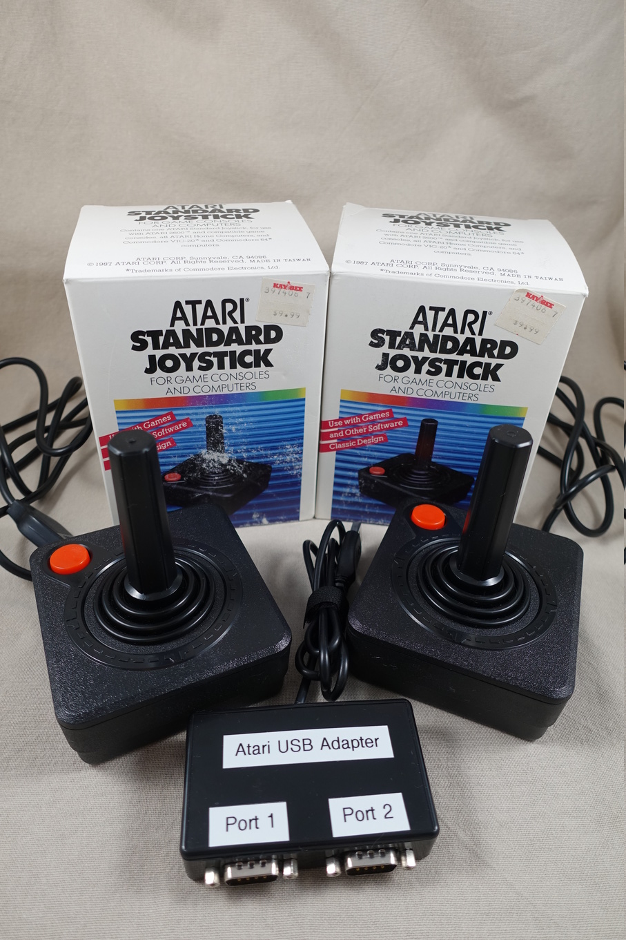
In order to make the adapter plug-and-play (no additional drivers) the VID/PID of the Pro Micro ATmega32U4 needs to be changed. Changing VID/PID will also enable multiple controller support on a single Pro Micro ATmega32U4.
Edit Arduino boards file - boards.txt
vi ~/.arduino15/packages/arduino/hardware/avr/1.6.23/boards.txtOr in my case
vi ~/projects/electronics/arduino/arduino-1.8.5/hardware/arduino/avr/boards.txt## leonardo.build.vid=0x2341
## leonardo.build.pid=0x8036
## leonardo.build.usb_product="Arduino Leonardo"
leonardo.build.vid=0x8282
leonardo.build.pid=0x3201
leonardo.build.usb_product="Retro Joystick Adapter"
lsusb
before - Bus 006 Device 018: ID 2341:8036 Arduino SA Leonardo (CDC ACM, HID)
after - Bus 006 Device 020: ID 8282:3201 Keio Retro AdapterFlash the following code onto Pro Micro ATmega32U4
Arduino Code - RetroJoystickAdapter_Atari.ino
//DB9-connector:
//C64/Sega Mastersystem: 1 = up, 2 = down, 3 = left, 4 = right, 6 = btn1, 8 = gnd, 9 = btn2
//MSX: 1 = up, 2 = down, 3 = left, 4 = right, 6 = btn1, 7 = btn2, 8 = gnd

//     define pins of Arduino:          UP, DOWN, LEFT, RIGHT, BTN1, BTN2
////const uint8_t inputPinsPort1[] =  {  5,    6,    7,     8,    4,   A2};
////const uint8_t inputPinsPort2[] =  { 10,   16,   14,    15,    3,   A1};

// my layout - begins
// DB9 joystick cable (front, looking at holes)
// 54321
// 9876

// DB9 joystick port (front, looking at pins)
// 12345
// 6789

// joystick 1
// 15 -> joystick 1 UP (1)
// 14 -> joystick 1 DOWN (2)
// 16 -> joystick 1 LEFT (3)
// 10 -> joystick 1 RIGHT (4)
// A1 -> joystick 1 POTY (5)  -Button3/PaddleB
// 9 -> joystick 1 FIRE (6)   -Button1/Button
// VCC -> joystick 1 +5V (7)
// GND -> joystick 1 GND (8)
// A0 -> joystick 1 POTX (9)  -Button2/PaddleA

// joystick 2
// 4 -> joystick 2 UP (1)
// 5 -> joystick 2 DOWN (2)
// 6 -> joystick 2 LEFT (3)
// 7 -> joystick 2 RIGHT (4)
// A3 -> joystick 2 POTY (5)  -Button3/PaddleB
// 8 -> joystick 2 FIRE (6)   -Button1/Button
// VCC -> joystick 2 +5V (7)
// GND -> joystick 2 GND (8)
// A2 -> joystick 2 POTX (9)  -Button2/PaddleA

// define pins of Arduino:          UP, DOWN, LEFT, RIGHT, BTN1, BTN2
const uint8_t inputPinsPort1[] =  { 15,   14,   16,    10,    9,   A0};
const uint8_t inputPinsPort2[] =  {  4,    5,    6,     7,    8,   A2};
// my layout - ends

//#define DEBUG

inline void translateState(uint8_t data, uint8_t *state) {
  state[0] = !bitRead(data, 4) | !bitRead(data, 5)<<1;
  state[1] = 127;
  state[2] = 127;
  if (!bitRead(data, 0)) state[2] = 0; /* up */
  if (!bitRead(data, 1)) state[2] = 255; /* down */
  if (!bitRead(data, 2)) state[1] = 0; /* left */
  if (!bitRead(data, 3)) state[1] = 255; /* right */
}


#include "HID.h"

#if ARDUINO < 10606
#error The Joystick2 library requires Arduino IDE 1.6.6 or greater. Please update your IDE.
#endif

#if !defined(USBCON)
#error The Joystick2 library can only be used with a USB MCU (e.g. Arduino Leonardo, Arduino Micro, etc.).
#endif

#if !defined(_USING_HID)
#error "legacy HID core (non pluggable)"
#endif

#define JOYSTICK_REPORT_ID  0x04
#define JOYSTICK2_REPORT_ID 0x05

#define JOYSTICK_STATE_SIZE 3

//================================================================================
//================================================================================
//  Joystick (Gamepad)

#define HIDDESC_MACRO(REPORT_ID) \
    /* Joystick # */ \
    0x05, 0x01,               /* USAGE_PAGE (Generic Desktop) */ \
    0x09, 0x04,               /* USAGE (Joystick) */ \
    0xa1, 0x01,               /* COLLECTION (Application) */ \
    0x85, REPORT_ID,          /* REPORT_ID */ \
    /* 2 Buttons */ \
    0x05, 0x09,               /*   USAGE_PAGE (Button) */ \
    0x19, 0x01,               /*   USAGE_MINIMUM (Button 1) */ \
    0x29, 0x02,               /*   USAGE_MAXIMUM (Button 2) */ \
    0x15, 0x00,               /*   LOGICAL_MINIMUM (0) */ \
    0x25, 0x01,               /*   LOGICAL_MAXIMUM (1) */ \
    0x75, 0x01,               /*   REPORT_SIZE (1) */ \
    0x95, 0x08,               /*   REPORT_COUNT (8) (full byte) */ \
    0x81, 0x02,               /*   INPUT (Data,Var,Abs) */ \
    /* X and Y Axis */ \
    0x05, 0x01,               /*   USAGE_PAGE (Generic Desktop) */ \
    0x09, 0x01,               /*   USAGE (Pointer) */ \
    0xA1, 0x00,               /*   COLLECTION (Physical) */ \
    0x09, 0x30,               /*     USAGE (x) */ \
    0x09, 0x31,               /*     USAGE (y) */ \
    0x15, 0x00,               /*     LOGICAL_MINIMUM (0) */ \
    0x26, 0xff, 0x00,         /*     LOGICAL_MAXIMUM (255) */ \
    0x75, 0x08,               /*     REPORT_SIZE (8) */ \
    0x95, 0x02,               /*     REPORT_COUNT (2) */ \
    0x81, 0x02,               /*     INPUT (Data,Var,Abs) */ \
    0xc0,                     /*   END_COLLECTION */ \
    0xc0                      /* END_COLLECTION */

static const uint8_t hidReportDescriptor[] PROGMEM = {
  HIDDESC_MACRO(JOYSTICK_REPORT_ID),
  HIDDESC_MACRO(JOYSTICK2_REPORT_ID)
};


class Joystick_ {

private:
  uint8_t joystickId;
  uint8_t reportId;
  uint8_t olddata;
  uint8_t state[JOYSTICK_STATE_SIZE];
  uint8_t flag;

public:
  uint8_t type;
  uint8_t data;

  Joystick_(uint8_t initJoystickId, uint8_t initReportId) {
    // Setup HID report structure
    static bool usbSetup = false;

    if (!usbSetup) {
      static HIDSubDescriptor node(hidReportDescriptor, sizeof(hidReportDescriptor));
      HID().AppendDescriptor(&node);
      usbSetup = true;
    }

    // Initalize State
    joystickId = initJoystickId;
    reportId = initReportId;

    data = 0;
    olddata = data;
    translateState(data, state);
    sendState(1);
  }

  void updateState() {
    if (olddata != data) {
      olddata = data;
      translateState(data, state);
      flag = 1;
    }
  }

  void sendState(uint8_t force = 0) {
    if (flag || force) {
      // HID().SendReport(Report number, array of values in same order as HID descriptor, length)
      HID().SendReport(reportId, state, JOYSTICK_STATE_SIZE);
      flag = 0;
    }
  }

};


Joystick_ Joystick[2] =
{
    Joystick_(0, JOYSTICK_REPORT_ID),
    Joystick_(1, JOYSTICK2_REPORT_ID)
};

//================================================================================
//================================================================================

void setup() {
  //set all DB9-connector input signal pins as inputs with pullups
  for (uint8_t i = 0; i < 6; i++) {
    pinMode(inputPinsPort1[i], INPUT_PULLUP);
    pinMode(inputPinsPort2[i], INPUT_PULLUP);
  }

  #ifdef DEBUG
  Serial.begin(115200);
  #endif
}

void loop() {

  Joystick[0].data = 0xff;
  Joystick[1].data = 0xff;

  for (uint8_t i = 0; i < 4; i++) {
    bitWrite(Joystick[0].data, i, digitalRead(inputPinsPort1[i])); //AXES1
    bitWrite(Joystick[1].data, i, digitalRead(inputPinsPort2[i])); //AXES2
  }

  bitWrite(Joystick[0].data, 4, digitalRead(inputPinsPort1[4])); //JOY1:FIRE1
  bitWrite(Joystick[0].data, 5, digitalRead(inputPinsPort1[5])); //JOY1:FIRE2
  bitWrite(Joystick[1].data, 4, digitalRead(inputPinsPort2[4])); //JOY2:FIRE1
  bitWrite(Joystick[1].data, 5, digitalRead(inputPinsPort2[5])); //JOY2:FIRE2

  #ifdef DEBUG
  Serial.print(" data0 j1: 0x"); Serial.print(Joystick[0].data, BIN);
  Serial.print(" data0 j2: 0x"); Serial.print(Joystick[1].data, BIN);
  Serial.println();
  delay(50);
  Serial.flush();
  #endif

  Joystick[0].updateState();
  Joystick[1].updateState();
  Joystick[0].sendState();
  Joystick[1].sendState();
  delayMicroseconds(500);
}
This project has been completed in late January of 2019.
Sources: